
Pumpjack VFD Control System: A Practical Guide to Smarter Oil Well Operation
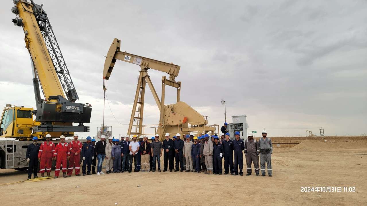
Pumpjacks often operate under changing well conditions. Fluid supply, polished-rod load, pump fillage and mechanical balance may vary over time, while a conventional fixed-speed pumping unit continues operating at the same stroke rate.
This mismatch can result in incomplete pump filling, unnecessary energy consumption, mechanical stress and additional maintenance work.
A pumpjack VFD control system uses a variable frequency drive, sensors and an industrial controller to adjust pumping speed according to actual operating conditions. The objective is not simply to slow down the motor. It is to coordinate the motor, pumping unit and well condition as one integrated system.
This guide explains how intelligent pumpjack control works, what information the system monitors, how to select the drive and motor, and what project information is required before specifying a solution.
What Is a Pumpjack VFD Control System?
A pumpjack VFD control system is an integrated automation solution for beam pumping units used in oil production.
A typical system may include:
- A variable frequency drive for motor speed and torque control
- An industrial controller for data processing and adaptive control
- Load and angular displacement sensors
- Motor speed and temperature monitoring
- Three-phase electrical measurement
- A local human-machine interface
- Alarm and operating-event records
- Ethernet, serial or wireless communications
- Connection to an oilfield SCADA system
The variable frequency drive controls the pumping unit motor, while the controller analyses mechanical, electrical and production data. Based on this information, the system can adjust operating frequency, stroke rate and operating mode.
The result is a pumping unit that responds more closely to the actual condition of the well.
Why Fixed-Speed Pumpjack Operation Can Be Inefficient
Many conventional pumping units operate at a fixed motor speed. However, the amount of fluid entering the wellbore does not always remain constant.
When fluid supply is insufficient, continuous fixed-speed operation may cause the pump to run faster than the well can fill. This can create several operating problems:
- Low pump fillage
- Unnecessary motor running time
- Increased mechanical loading
- Additional stress on belts, gearboxes and sucker rods
- Higher energy consumption per unit of production
- More frequent inspection and maintenance
- Limited visibility into abnormal well conditions
Traditional systems may rely heavily on manual inspections or periodic tests. These methods provide useful information, but they do not continuously adjust the pumping unit as conditions change.
An intelligent VFD system introduces closed-loop control, allowing the pumping rate to follow the well’s production condition more closely.
How Intelligent Pumpjack Control Works
The control process can be understood in four stages.
1. Capture the well and equipment condition
Sensors and measurement modules collect relevant operating data, which may include:
- Polished-rod load
- Angular displacement
- Stroke and strokes per minute
- Motor speed
- Motor temperature
- Cabinet temperature and humidity
- Three-phase voltage and current
- Active power and power factor
- Fan operating current
- Pump fillage
- Motor balance condition
Additional downhole or process sensors may be integrated when the project requires measurements such as fluid level, oil pressure, water content or flow.
2. Analyse the operating data
The controller combines displacement and load data to generate and analyse the surface dynamometer card.
Electrical and mechanical parameters help the system identify operating conditions such as:
- Insufficient fluid supply
- Unbalanced pumping-unit operation
- Belt slip
- Motor overload
- Sucker-rod sticking or possible breakage
- Pump-loss conditions
- Abnormal cabinet temperature
- Cooling-fan faults
- Phase loss or phase reversal
- Communication failure
The actual diagnostic scope depends on the selected sensors, controller configuration and site requirements.
3. Adjust motor output
The variable frequency drive changes the motor speed and pumping frequency according to the controller command.
Instead of running continuously at a fixed speed, the system may:
- Reduce the pumping rate when well inflow is low
- Increase the rate within an approved operating range when conditions permit
- Use low-speed continuous operation
- Apply intermittent pumping strategies
- Adjust the speed profile within a pumping cycle
- Provide controlled acceleration and deceleration
- Reduce starting current and mechanical shock
Operating limits must be configured according to the motor, gearbox, pumping unit and well conditions. Intelligent control should always remain within the safe mechanical and electrical range of the equipment.
4. Connect local and remote operations
The local HMI displays the system status and allows authorised personnel to review parameters and alarms.
Depending on the communication configuration, the system can also exchange information with an oilfield SCADA platform through:
- Ethernet
- RS232 or RS485
- Modbus RTU
- 4G or 5G
- ZigBee
- LoRa
- Industrial radio communication
Remote access can help operators compare wells, review historical operating data and prioritise field maintenance.
Core Functions of a Pumpjack Automation System
A complete pumpjack automation system should do more than control motor frequency.
Adaptive stroke-rate control
The controller evaluates changes in the well and adjusts the pumping frequency within the configured limits.
Historical dynamometer-card and electrical data can also support the refinement of operating parameters over time.
Motor soft starting
The drive accelerates the motor progressively, reducing the current and mechanical shock associated with direct-on-line starting.
This is especially important for pumping units with high inertia and cyclic loads.
Mechanical and electrical protection
Depending on the project configuration, protection functions may include:
- Overcurrent and overvoltage protection
- Motor overload and overtemperature protection
- Ground-fault and phase-fault monitoring
- Overspeed protection
- Emergency stop
- Belt-slip monitoring
- Cabinet-temperature alarms
- Cooling-fan monitoring
- Communication-failure alarms
Protection thresholds must be coordinated with the motor, variable frequency drive and upstream electrical system.
Dynamometer-card monitoring
The HMI can display the dynamometer card together with stroke, polished-rod load, strokes per minute, pump fillage and motor balance information.
These data help production and maintenance teams understand how the surface equipment and downhole pump are operating.
Electrical energy monitoring
The system can monitor three-phase voltage, current, power and accumulated electrical energy.
Combining electrical data with production information provides a clearer view of energy use and equipment loading than reviewing motor current alone.
Alarm and operation history
Parameter changes, operating events and alarm records can be retained for troubleshooting and maintenance analysis.
This helps maintenance personnel identify recurring conditions instead of relying only on the alarm visible at the time of inspection.
Selecting a Variable Frequency Drive for a Pumpjack
Selecting a variable frequency drive for a pumpjack requires more than matching the motor kilowatt or horsepower rating.
The following factors should be evaluated.
Motor rated current
Drive sizing should be checked against the motor’s rated current, not only its nominal power.
Ambient temperature, altitude, switching frequency and enclosure conditions may require derating.
Starting and cyclic torque
A beam pumping unit creates a cyclic load. The drive must provide sufficient starting torque and short-term overload capacity while maintaining stable current control.
Regenerative energy
During part of the pumping cycle, the mechanical load may drive the motor and return energy to the DC bus.
The system may therefore require a braking unit and braking resistor. In some projects, a regenerative drive solution may also be considered.
Supply voltage and grid conditions
The drive must match the site voltage, frequency and allowable voltage variation.
Power-quality requirements, harmonics, transformer capacity and generator operation should be reviewed during the engineering stage.
Environmental conditions
Oilfield installations may be exposed to:
- High or low temperatures
- Dust and sand
- Solar radiation
- Humidity
- Corrosive atmospheres
- High altitude
- Hazardous-area requirements
The control cabinet, cooling system, component selection and protection level should be engineered for the actual installation environment.
Wolong’s WD200 low-voltage drive platform supports asynchronous and permanent-magnet synchronous motors and provides V/F and vector-control modes. The final drive configuration should be selected according to the motor, pumping-unit load, environment and control requirements.
Learn more about the Wolong WD200 variable frequency drive.
Selecting the Right Pumpjack Motor
The motor is a critical part of the complete pumpjack drive system. Search terms such as “pumpjack motor” or “oilfield pumping unit motor” may refer to different motor constructions depending on the region, hazardous-area classification and operating method.
High-slip motors for beam pumping units
Beam pumping units experience cyclic and fluctuating torque. A high-slip motor can soften the mechanical response to load changes and make the pumping unit easier to start.
Wolong NEH Series NEMA Design D motors are designed for beam pumping-unit applications. Their high starting torque and high-slip characteristics are intended to accommodate fluctuating pumpjack loads.
When combined with a VFD, the motor and drive should be evaluated together. The acceptable speed range, cooling, insulation, bearing arrangement and torque requirements must all be confirmed.
Variable-frequency motors for oilfield equipment
For oilfield applications requiring variable-speed operation, a variable-frequency three-phase asynchronous motor should be selected according to:
- Required torque across the speed range
- Motor cooling at reduced speed
- Insulation suitability for PWM output
- Cable length between the drive and motor
- Encoder requirements
- Ambient temperature
- Ingress-protection level
- Hazardous-area classification
Depending on the project and regional standard, Wolong motor options may include high-slip pumping-unit motors, premium-efficiency variable-frequency motors and explosion-protected motors.
Explosion-proof and hazardous-area motors
Some oil and gas installations require certified hazardous-area equipment.
The required motor protection concept depends on the gas group, temperature class, zone or division, installation location and local regulations.
Examples within Wolong’s motor portfolio include:
- IEC explosion-protected motors for oil and gas applications
- Zone 2 non-sparking motors
- NEMA Division 1 explosion-proof motors
- Division 2 variable-frequency motors
- High-slip NEMA Design D motors for beam pumping units
Certification must be verified for the exact motor model and target market. A product family description should never be treated as confirmation that every rating carries the same approval.
Explore Wolong industrial motor and drive products.
SCADA and Remote Oil-Well Monitoring
Connecting the pumping unit to SCADA allows operating data to be viewed beyond the local cabinet.
A connected system can provide:
- Real-time operating status
- Motor speed and output frequency
- Voltage, current and power data
- Dynamometer-card information
- Pump fillage and balance data
- Active alarms
- Historical trends
- Parameter-change records
- Running time and energy statistics
Remote monitoring does not eliminate the need for field inspection. It helps production and maintenance teams decide which wells require attention first and what information should be checked before personnel arrive on site.
Cybersecurity, user permissions, communication reliability and data ownership should be defined during project engineering.
Operational Benefits
A correctly engineered pumpjack VFD control system can provide several operational advantages.
Better alignment with well inflow
The pumping rate can be adjusted to reflect changing well conditions instead of remaining fixed.
Reduced mechanical stress
Controlled starting, stopping and speed adjustment can reduce abrupt mechanical loading on belts, gearboxes and the rod string.
Improved maintenance visibility
Alarm history, dynamometer cards and electrical trends provide more information for troubleshooting.
More flexible operation
Operators can configure continuous, low-speed, intermittent, local or remote operating modes according to the project requirements.
Potential energy reduction
Reducing unnecessary operating speed or running time may reduce energy consumption.
However, energy savings depend on the original operating method, well inflow, pumping-unit condition, motor efficiency and production target. Savings should therefore be evaluated using actual site data rather than a universal percentage claim.
Information Required Before Selecting a Solution
To prepare a reliable pumpjack drive and control proposal, the supplier should receive the following information:
- Pumping-unit manufacturer and model
- Motor power, voltage, current, speed and efficiency
- Motor type and existing certification
- Gearbox and pulley information
- Stroke length and current stroke rate
- Polished-rod load
- Existing dynamometer-card data
- Well-production and pump-fillage information
- Site voltage and frequency
- Ambient temperature and altitude
- Hazardous-area classification
- Required enclosure-protection level
- Communication and SCADA protocol
- Existing sensors
- Required operating and protection functions
- Preference for continuous or intermittent pumping
The more complete the project information, the more accurately the motor, drive, braking system, sensors and controller can be selected.
Frequently Asked Questions
Can a VFD be installed on an existing pumpjack?
In many cases, yes. However, the existing motor, gearbox, electrical supply, control cabinet, braking requirements and mechanical condition must be checked before retrofit.
Does a pumpjack VFD always save energy?
No fixed saving can be guaranteed for every well. The result depends on the original operating method, well inflow and selected control strategy.
The main opportunity is to reduce unnecessary speed or running time while maintaining the required production target.
What motor is suitable for a beam pumping unit?
The motor must provide adequate starting and cyclic torque and must suit the environmental and hazardous-area requirements.
High-slip NEMA Design D motors are commonly considered for beam pumping units, while variable-frequency or explosion-protected motors may be required for other project conditions.
Can the system generate a dynamometer card?
Yes. A configured system can use load and displacement measurements to generate a surface dynamometer card and display related data such as stroke, polished-rod load, pump fillage and motor balance.
Can multiple pumpjacks be monitored remotely?
Yes. Ethernet, serial or wireless communication can connect individual control systems to a central SCADA platform. The network architecture and cybersecurity requirements should be confirmed during engineering.
What happens if communication is lost?
The local controller and drive should be configured to continue safe operation or enter a defined fallback state. The appropriate response depends on the process and the customer’s operating philosophy.
Build a Pumpjack Control Solution Around Your Well Conditions
A pumpjack VFD control system should be designed around the well, pumping unit, motor and operating environment—not selected from motor power alone.
Wolong combines variable frequency drives, industrial motors, control technology, sensing, HMI and communication capabilities to support integrated pumping-unit control projects.
Review the complete Intelligent Pumpjack Control Solution, or contact Wolong Drives with your motor data, pumping-unit parameters and operating requirements.